
Brainvision hacks
This page last updated 2024/02/19
Introduction
This is a list and explanation of some hardware hacks for brainvision products, specifically the actichamp line of products. Some of this information could be used to repair, repurpose, or upgrade old hardware.
Auxiliary input hardware
Building custom AUX hardware for the actichamp is relatively easy. The AUX ports built into the actichamp are BINDER Female 5-pin panel mount connectors, Part #s 09 9792 30 05 or 09 9792 20 05 and custom hardware can be built off of the handful of options for the matching male connectors: two with cables (2 meters #77 7095 0000 10005-0200, and 5 meters #77 7095 0000 10005-0500), and two without (standard #09 9789 71 05 and slim #09 9789 00 05).
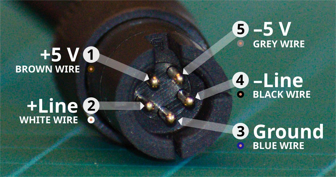
Pinout for the male binder cables noted in the paragraph above. With the notch oriented up, (1) is top left, numbers ascend counter-clockwise. (1) is +5V power, (2) is positive polarity recorded signal, (3) is ground or neutral voltage to which the signal should be compared. (4) is the negative polarity recorded signal, (5) is -5V power. Wire colours are only applicable to the connectors above with cables. Note female pinout on the amplifier itself is the mirror image of this pinout; (1) would be on the top right (notch oriented up), with numbers ascending clockwise.
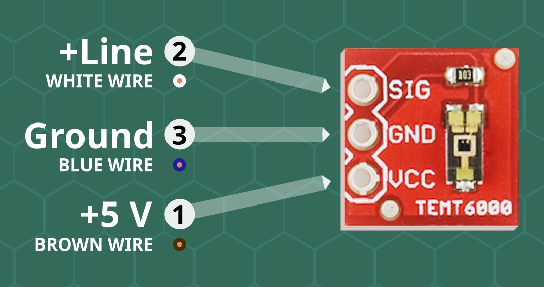
Photosensor wiring diagram. The photosensor depicted is a SparkFun Ambient Light Sensor Breakout, TEMT6000. More intense incoming light results in a higher analog voltage on the signal pin. VCC on the photosensor should be connected to the (1) +5V pin, ground to (3) ground, and the photosensor signal channel should be connected to the (2) +Line.
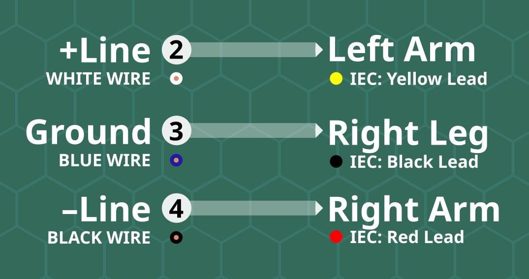
Electrocardiogram (ECG) wiring diagram. International Electrotechnical Commission (IEC) lead colours are presented in the figure. The equivalent lead colours for the American Heart Association (AHA) would be Black-Green-White, instead of Yellow-Black-Red, respectively. If constructing an ECG lead, I suggest using snap electrode leads and the complementary snap foam electrodes typically used for ECG administration.
Note on Polarity
Brainvision software often shows positive polarity down. You can address this in Brainvision Recorder under Configuration > Preferences > Scaling and deselecting 'Polarity: Positive Down'. Be aware of this setting before presuming e.g. your ECG leads are misplaced.
Photosensor Types
The photosensor visualized above is a photoresistor. Brainvision's brainded photosensor is a photodiode. Brainvision has some notes on their website about the photosensor technology here. They correctly identify that photodiodes are more sensitive than photoresistors. However they also demonstrate the photodiode sensitivity, low-pass filtering the data to improve signal quality, then argue that photoresistors are not suitable technology because their hardware causes them to intrinsically low-pass filter their signal. For simple timing purposes where the sampling frequency exceeds the display refresh rate, photoresistors are more than capable of producing post-hoc time locking. It is not difficult to utilize some sample stimuli to understand the nature of the photoresistor response, and account for that in postprocessing. More advanced experiments relying on more interactive signalling would conceptually benefit from the more sensitive photodiode.
Refurbishing the Powerpack
The older Brainvision Powerpacks contain sealed 3-cell lead-acid batteries. Specifically, they contained a 6V 6.5Ah Exide A506/6,5 S. The battery itself is not particularly remarkable, but it's size is, if you intend on replacing the battery while maintaining the form factor. The original Exide battery is 5-15/16×3-11/16×1-5/16" or approximately 150×95×35mm. Not the most common 6V battery size, but RS Power's RS67 6V 7.2Ah and AJC's C7S 6V 7Ah batteries are almost identical fits with the original. The original battery is attached to the charger board with female spade terminals (on the board side) and it is very simple to remove and swap out a different battery. I would not assume that the battery pack remains MR compatible, if it was already, and this will most definitely void the warranty.
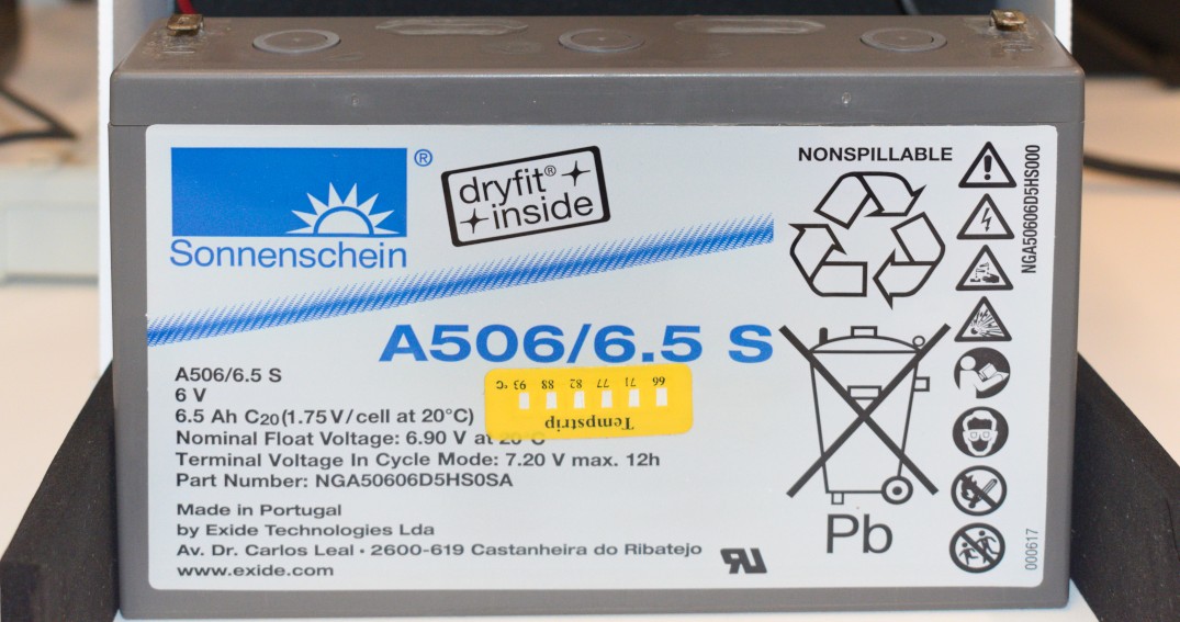
Original battery inside the powerpack.
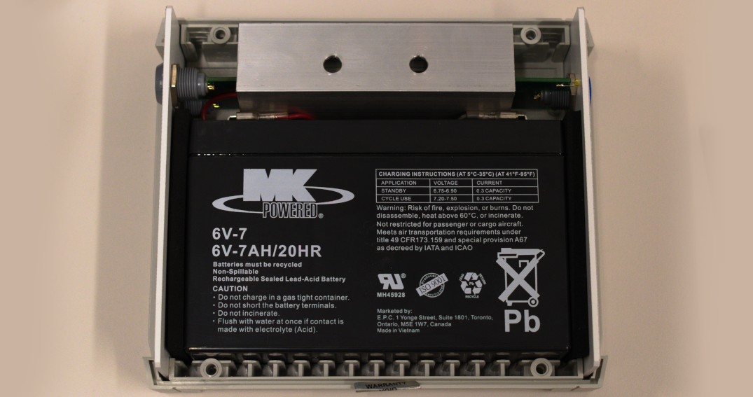
Replacement battery fit.
Change log
2024/02/19: Updated links to Binder cables, original version discontinued. Added polarity & and photosensor notes.
2023/07/01: Initial version w/ AUX setup and powerpack battery replacement.